
Trough Idler Angle Selection: 20°, 25°, or 35° for Your Belt Width
Three trough angles dominate carrying idler specifications: 20°, 25° and 35°. The angle at which the outer rollers of a carrying idler set are inclined decides how deeply the belt is formed into a trough — and that one geometric choice controls how much material stays on the belt, how hard the belt is flexed at every idler station, and how much rotational resistance the rollers add to the drive.
This article is written for buyers, project engineers and maintenance planners who are specifying right now. It explains what the trough angle actually controls, what the governing standards say, how the ER-TROUGH-108 trough carrying idler is configured across 20°, 25° and 35° options (tube diameters Ø89 mm, Ø108 mm and Ø133 mm; shaft sizes Ø20 mm and Ø25 mm; sealed double-row bearings), and how to move from an angle decision to a delivered batch that passes inspection.
Shanghai Eastrise Trading Co., Ltd. (sh-eastrise.com) is a Shanghai-based foreign-trade enterprise that supplies mining accessories, including conveyor idler rollers, through its own manufacturing factories, in a chain that covers in-house R&D, standardized production, quality testing and worldwide export services.
Problem definition: what the trough angle actually decides
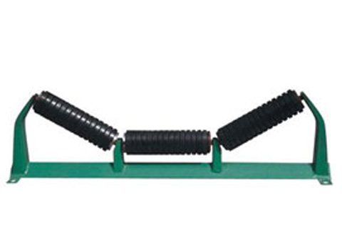
A trough angle is the inclination of the two outer — wing — rollers of a three-roller carrying set relative to the horizontal plane. A 20° set forms a shallow trough, a 25° set an intermediate one, and a 35° set the deepest of the three common configurations. The centre roller stays horizontal in all three cases; the angle changes how the belt is supported between the outer rollers and how much side-wall support the load receives.
Three effects follow from that geometry, and they pull in different directions:
- Material containment. A deeper trough increases the material cross-section the belt can carry at the same belt width and holds the load away from the belt edges. This is why lumpy, abrasive or unevenly fed material is normally run in a deeper trough.
- Belt flexing and edge stress. Every time the belt passes an idler station it is bent from flat into the trough and back again. The sharper the angle, the greater the flexing at the wing-roller junctions and the more tension is concentrated along the belt edges. Belts with a stiff carcass, or belts that are narrow relative to their tension rating, tolerate this less well.
- Running resistance and roller loading. A deeper trough changes the direction of the load carried by the wing rollers, which changes the load seen by the bearing and the seal. Rotational resistance at each idler contributes to the conveyor's total resistance, so a roller that keeps turning freely under load matters more as the trough deepens.
When the angle and the belt do not match, the symptoms tend to be visible: spillage along the line rather than only at the loading point, material rolling back inside the trough on inclined sections, belt edge damage and tracking problems after the belt leaves the troughing transition, and rollers that run hot or noisy well before the expected replacement interval.
It helps to keep the roller family in view, because trough angle applies to one position only. Trough (carrying) rollers and return rollers are specified separately; impact rollers protect the loading point; guide rollers and self-aligning rollers control belt tracking. A trough angle change therefore rarely stands alone — it is one parameter inside a set that also includes roller diameter, shaft size, bearing and seal configuration, and material of construction.
Industry background: where trough idlers sit today
Conveyor rollers remain a steel-dominated component. Steel accounted for 64% of the global conveyor roller material market share in 2024, according to Straits Research. That point matters for trough angle selection because shell diameter and shell stiffness determine how much load a steel roller carries without deformation when the belt is formed into a deep profile.
The sector with the most to lose from a poorly chosen angle is mining and quarrying, which represented 36% of rollers and idlers revenue in 2024 (Straits Research). Cement plants and bulk ports follow closely. Typical duty in these settings is dusty, heavy-duty and continuous: mining ore conveyor lines commonly run 24/7, cement raw-material handling combines heavy dust with medium-to-high temperatures, and bulk terminals operate outdoors in humid, salt-spray conditions over long conveying distances.
Market size figures for this component should be read with care, because the underlying definitions differ. Straits Research values the rollers and idlers segment at USD 4.14 billion in 2025, projected to reach USD 7.05 billion by 2034. A narrower “conveyor roller” definition produces a much smaller figure — Cognitive Market Research estimated USD 115.9 million for 2024, as recorded in the same verified data set. The gap is a scope difference between a component and a sub-system rather than a contradiction. The practical implication for a buyer is straightforward: trough idlers are a small share of project spend and a disproportionate share of downtime risk.
Three standards shape how troughing idlers are specified and tested:
- ISO 5048:1989 — the international standard for calculating power and tension in belt conveyors with carrying idlers, which ties idler resistance into drive sizing.
- CEMA Standard No. 502-2022 — dimensional standards and load ratings for bulk material belt conveyor troughing and return idlers, widely referenced in North America.
- DIN 22112 Part 3 (1996) — testing requirements for belt conveyor idlers used in underground coal mining.
Naming the applicable standard in the purchase order is what makes inspection scope enforceable. A trough angle agreed verbally is not a specification.
Detailed solution: the trough carrying idler and its 20°/25°/35° options
The ER-TROUGH-108 is a trough carrying idler supplied in three trough angles — 20°, 25° and 35° — so the same roller platform can serve different containment requirements without changing the frame philosophy. The 35° configuration is the deep-trough version: it forms the belt into the tightest of the three profiles, which is the practical answer when the problem being solved is material escaping from a fully loaded belt.
Dimensional and configuration parameters are as follows:
| Parameter | Available options |
|---|---|
| Trough angle | 20°, 25°, 35° |
| Tube (shell) diameter | Ø89 mm, Ø108 mm, Ø133 mm |
| Shaft diameter | Ø20 mm, Ø25 mm |
| Bearing arrangement | Sealed double-row bearings |
| Roller position | Carrying (loaded) run, three-roller troughing set |
| Inspection basis | Full-batch inspection: dimensions, appearance, radial runout, rotational resistance, quantity, packaging |
| Order route | Drawing confirmation or approved sample; optional third-party inspection |
The tube diameters are not interchangeable alternatives chosen by preference. Ø89 mm, Ø108 mm and Ø133 mm are matched to belt width, belt speed and load per idler station, and to the shaft size the frame is drilled for. Ø20 mm and Ø25 mm shafts correspond to different load paths, and changing shaft size changes the end-bracket fit — which is why the shaft and tube decision normally has to be locked before the trough angle is finalised.
Sealed double-row bearings and vibration control
At 35°, the wing rollers carry a more steeply inclined load than at 20°, and any free play inside the bearing assembly shows up as vibration rather than as clean rolling motion. Sealed double-row bearings reduce that play by spreading the radial load across two rows of rolling elements inside the same housing, while the seal keeps dust and moisture away from the grease film. On a dusty line, the practical result is that rotational resistance stays stable instead of rising as contamination builds.
Whether that stabilisation is achieved depends on how tightly the finished roller is controlled. Eastrise comparison data recorded against competitor rollers using labyrinth seals cites 22% lower runout tolerance and 13 dB lower running noise; the same comparison data recorded against low-cost conventional steel rollers cites 25% lower runout deviation with a stated three-times longer service life. These are manufacturer comparison figures and should be read as such — but the variables they point to, runout and sealing, are exactly the ones that decide whether a 35° trough runs smoothly or feeds vibration back into the conveyor frame.
Full-batch inspection
Precision claims are only as good as the inspection behind them. The relevant practice is full-batch inspection rather than sample-only checking: dimensions, appearance, radial runout, rotational resistance, quantity and packaging are verified before shipment, and inspection records are available. Third-party inspection can be arranged when the contract requires it, with acceptance criteria stated in the contract rather than agreed informally.
Step-by-step breakdown: from trough angle decision to installed batch
The sequence below works for both a new conveyor and a retrofit in which existing idlers are being replaced.
Step 1 — Characterise the material, not just the product name
Record lump size distribution, moisture content, bulk density, abrasiveness and how evenly the material is fed. Fine, free-flowing material behaves differently from coarse, lumpy, unevenly fed ore, and it is the material that decides how much side-wall support the trough must provide.
Step 2 — Record the belt and the frame as they actually are
Note belt width, belt construction and cover grade, belt speed, and the existing idler set: the trough angle already in use, roller length, tube diameter and shaft diameter. This is where the Ø89/108/133 mm and Ø20/25 mm options get fixed. A trough angle change that also changes shaft diameter means frame brackets change too, which turns a roller replacement into a structural job.
Step 3 — Choose the angle against the constraint you actually have
- 20° — shallow trough. Suited to fine, free-flowing, evenly fed material, and to situations where belt edge stress and belt stiffness are the limiting factors. Containment is lower than at 25° or 35°, so spillage control depends more on loading discipline and skirt design.
- 25° — intermediate trough. The general-purpose option where the material is mixed and neither maximum containment nor minimum belt flexing dominates. It is frequently the angle already installed on existing lines, which also makes it the least disruptive retrofit.
- 35° — deep trough. Applied where containment is the priority: lumpy or heavy material, high-capacity lines, and belts wide enough to accept the deeper profile. It delivers the largest material cross-section of the three on the same belt width, at the cost of more flexing at the wing-roller junctions and a more inclined load on the wing-roller bearings.
Step 4 — Check the transition zones and the loading point
Between the pulley and the fully troughed carrying run, the belt is pulled from flat into the trough profile. The shorter that distance, the more the belt edges are stretched at any given trough angle, so trough angle and transition length have to be reviewed together. The loading point itself is normally protected by impact rollers rather than by carrying idlers. On an inclined conveyor, review the profile at the same time: a trough that is adequate on the horizontal run may not hold the load where the belt climbs.
Step 5 — Confirm the drawing before production
Drawing confirmation is the point where trough angle, tube diameter, shaft diameter, roller length and sealing arrangement stop being assumptions. For a first order or a first article, sample approval is the practical alternative: an approved sample or an approved drawing becomes the reference against which the batch is checked.
Step 6 — Fix the acceptance criteria in the order
State the inspection scope in the purchase order — dimensions, appearance, radial runout, rotational resistance, quantity and packaging — plus third-party inspection if required. Acceptance criteria belong in the contract, and inspection records should travel with the shipment.
Step 7 — Commission, then standardise
After installation, check that the belt trains correctly through the transition, that no idler runs hot or noisy, and that spillage has reduced where it was expected to. Once a configuration is proven, standardise it across the line and keep the drawing on file. That is what allows a replacement batch to match the installed idlers years later without re-measuring the frame.
Use cases: matching trough angle to operating reality
Mining ore conveyor lines. Dusty, heavy-duty, continuous duty. Containment is the driver, so the deep 35° configuration is the usual starting point, with sealed bearings selected for dust resistance and stable rotational resistance across long running hours.
Cement raw-material handling. Heavy dust, medium-to-high temperatures and continuous operation. The priority is stable support with less belt mistracking and lower maintenance frequency; a 25° or 35° trough is selected according to how lumpy the feed is, and the idler specification is confirmed against the actual operating temperature range rather than assumed.
Bulk terminals and ports. Outdoor operation with humidity and salt spray over long conveying distances. Containment still matters, but so does corrosion behaviour: a 25° trough with corrosion-resistant treatment and sealed bearings is often the balance point, and low running noise becomes a measurable operating benefit on long lines.
Underground coal. Where the project falls under European practice, DIN 22112 Part 3 (1996) defines the testing requirements for belt conveyor idlers used underground, so the trough angle decision is made inside that test framework.
Quarry and heavy-duty industrial conveying. Mixed lump sizes and shock loading at the crusher discharge point. The angle decision is paired with impact rollers at the loading zone, with trough carrying idlers doing the work along the carrying run.
Comparison table: 20°, 25° and 35° trough angles side by side
| Trough angle | Trough depth / containment | Belt flexing and edge stress at idler junctions | Load direction on wing rollers | Typical fit | Points to verify |
|---|---|---|---|---|---|
| 20° | Shallowest of the three | Lowest | Least inclined | Fine, free-flowing, evenly fed material; belt stiffness or edge stress is the constraint | Spillage along the line; loading discipline and skirt design |
| 25° | Intermediate | Moderate | Moderate | Mixed bulk materials; general-purpose conveying; retrofit of existing lines | Whether the existing frame, tube diameter and shafts already match |
| 35° (deep-trough configuration) | Deepest of the three | Highest | Most inclined | Lumpy or heavy material, high-capacity lines, containment-critical runs | Belt width and carcass suitability; transition length; bearing and sealing specification |
FAQ
Which standards should a trough carrying idler comply with?
Three documents are commonly referenced. ISO 5048 (1989 Edition) provides the international standard for calculating power and tension in belt conveyors with carrying idlers, so it links idler resistance to drive sizing. CEMA Standard No. 502-2022 establishes dimensional standards and load ratings for bulk material belt conveyor troughing and return idlers and is widely applied in North America. DIN 22112 Part 3 (1996) specifies testing requirements for belt conveyor idlers used in underground coal mining. Which document governs your order depends on destination market and end use, and it should be named in the purchase order so that inspection scope is unambiguous.
How do I choose between 20°, 25° and 35° trough angles for my belt width?
Choose against the constraint that is actually binding. If belt edge stress or belt stiffness is the limit — typically with fine, free-flowing material — the shallow 20° profile keeps flexing at the roller junctions lowest. If the material is mixed and the line is general-purpose, 25° is the middle option and is usually the least disruptive choice for a retrofit. If containment is the problem — lumpy or heavy material, high capacity, spillage along the line — the 35° configuration of the ER-TROUGH-108 forms the deepest trough and carries the largest material cross-section on the same belt width. Because belt width, belt construction and material feed interact, the practical route is to confirm the angle against the actual belt width and material profile, then verify with a trial idler set before ordering a batch.
What determines the price and the minimum order quantity of a trough carrying idler?
Quotation follows the confirmed specification rather than the product family: trough angle (20°, 25° or 35°), tube diameter (Ø89 mm, Ø108 mm or Ø133 mm), shaft diameter (Ø20 mm or Ø25 mm), sealing and bearing configuration, roller length, quantity and packaging. The standard ordering route carries a minimum order quantity of 10 units, while a model-confirmation route is available with a minimum of 2 units. Payment is by T/T — typically 30% deposit with 70% before shipment — and delivery can be arranged on FOB, CIF or EXW terms, with both full container load and less-than-container load shipments supported and export documents provided.
Can I test a trough idler before committing to a full order?
Yes. Two validation routes are used. The first is drawing confirmation, in which trough angle, tube diameter, shaft diameter, roller length and sealing arrangement are agreed on a drawing before production. The second is sample approval, in which a customer-approved sample becomes the reference for the batch. Acceptance for these orders is based on the approved sample or drawing confirmation, with inspection records available, and sample payment terms are confirmed with the order. Courier, air freight and sea freight are all supported for sample and trial shipments.
How do I select a long-term mining conveyor roller supplier for belt conveyor projects?
Look for four things. First, control of production: a supplier that runs its own manufacturing chain — in-house R&D, standardized production, quality testing and export services — is less exposed to third-party variation than an intermediary. Second, a documented inspection routine that applies to every batch, with records, not to samples only. Third, a spare-parts route that keeps the proven drawing on file so replacement batches match the installed idlers. Fourth, a relationship record consistent with your region and project rhythm. Shanghai Eastrise Trading Co., Ltd. operates its own manufacturing factories with an 11,000 m² facility, approximately 50 staff, a 10-engineer R&D team and an annual production capacity of 2,000 tons; export business accounts for 20% of total sales, and the company has built long-term, stable and mutually trusted cooperative relationships with clients from Southeast Asia, Central Asia, Russia and other overseas markets, with OEM and ODM support for customer-specific parameters. To move forward, send your belt width, material profile, target trough angle and required quantity to jone.liu@sh-eastrise.com or via WhatsApp at +86 18516552763, or download the product brochure for the full component list.
Conclusion
Trough angle selection is a small decision with a long operational tail. 20° keeps belt flexing low and suits fine, evenly fed material; 25° is the general-purpose middle; 35° forms the deepest trough and is the practical answer when containment of lumpy or heavy material is the constraint. What makes the choice hold up is the execution around it — matching tube diameter and shaft size to the belt and frame, specifying sealed double-row bearings where dust and vibration are real, fixing inspection scope in the order, and keeping the approved drawing so that the next batch matches the last.
For a project where the angle needs to be tested rather than assumed, the ER-TROUGH-108 is available in all three angles, so a trial set can be run on the actual belt width before the batch order is placed.
Next step: request a trough idler sample or quotation
Send belt width, material profile, target trough angle and required quantity. Shanghai Eastrise will confirm the drawing and the inspection scope before production begins.
Email: jone.liu@sh-eastrise.com | Tel / WhatsApp: +86 18516552763 | Chat on WhatsApp
Address: No. 2458 Dongda Road, Lingang New Zone, China (Shanghai) Pilot Free Trade Zone
Product brochure: download the Eastrise brochure
Have Questions or Need More Details?
Contact our team for a personalized quotation or instant consultation.
Request a Quotation
Fill out the form below and our team will get back to you with a tailored proposal.
WhatsApp Direct Chat
Prefer to chat in real-time? Message us on WhatsApp for instant assistance & quick answers.
- Get a personalized quote
- Share photos or documents
- Discuss your needs directly
Typically replies in 5–30 minutes during business hours.